Last July, a 150 kW rooftop array in Arizona experienced a string-level arc fault. The inverter’s internal detection circuit eventually tripped, but not before a molten copper splash damaged three adjacent modules and forced a four-day shutdown. The post-incident report pointed to a single cause: a poorly coordinated overcurrent protection strategy on the DC side. The inverter wasn’t the problem; the missing layer of fusing and fault isolation upstream was.
Stories like this are becoming distressingly common. As string currents climb past 15 A in modern high-efficiency panels, the solar industry is waking up to a difficult truth—traditional AC-centric safety approaches leave significant gaps on the DC side. Addressing those gaps doesn’t require complex control algorithms; it requires revisiting a foundational component that many installers treat as a simple pass-through enclosure.
When Overcurrents Become Fire Hazards in Solar Installations
The conversation around PV safety often revolves around rapid shutdown and arc-fault circuit interrupters (AFCIs) at the inverter. While these are essential, they don’t address what happens when a panel develops a fault and backfeeds current into a faulted string. Unlike AC circuits, a photovoltaic source is current-limited by nature. A short circuit in one string may barely exceed the operating current of the remaining paralleled strings, sitting in a dangerous grey zone where a standard thermal-magnetic breaker will never trip—yet fault currents can still exceed the ampacity of the module’s interconnecting cables.
According to IEC 62446-1, the de facto standard for PV system documentation and maintenance, any string configuration with three or more parallels requires overcurrent protection per string. Yet field audits by third-party engineering firms consistently reveal that this rule is either misunderstood or deliberately ignored, especially in smaller commercial systems. “We regularly find unfused combine units where three or four strings are paralleled without any individual string fusing,” notes one NABCEP-certified inspector in a 2023 industry webinar. “The installer assumes the inverter will handle it. That’s not how DC fault conditions work.”
The physics is unforgiving: a single faulted module can draw reverse current from every healthy parallel string, turning a small hotspot into a cascading thermal event. Insulation breakdown, connector melting, and—in the worst case—a sustained arc follow. None of this will trigger an AC-side breaker. The only defense is a properly rated string fuse inside a dedicated DC collection point.
Why Traditional Protection Methods Fall Short on the DC Side
Moving beyond simple fusing, the DC strings in PV systems face a second, less visible adversary: transient overvoltage from lightning or grid switching. A 2022 study by the Fraunhofer Institute for Solar Energy Systems ISE found that surge damage accounts for roughly 18% of all non-mechanical inverter failures in central Europe, with induction loops in long DC cable runs acting as efficient collectors of electromagnetic pulses.
What confuses the market is the certification label. A UL 1741-listed inverter inherently provides some level of ground-fault detection and anti-islanding, but it offers no specific protection for the string cables extending across a roof. Type 2 surge protective devices (SPDs), tested to IEC 61643-31, become a mandatory line of defense as soon as cable lengths exceed 10 meters or when an installation falls under the scope of IEC 62305 lightning protection zones. Yet they are frequently omitted from BoS (balance of system) budgets.
This is where a structured DC aggregation enclosure fundamentally changes the risk profile. Instead of placing unfused pigtails directly into a string inverter, installers can route each input through an individual fuse holder and an SPD in a single weatherproof housing. The approach decouples protection from inverter topology, enabling compliance with NEC 690.9 and local fire codes without relying on the inverter manufacturer’s pre-defined string configuration.
Centralizing Safety Functions: Beyond Mere String Aggregation
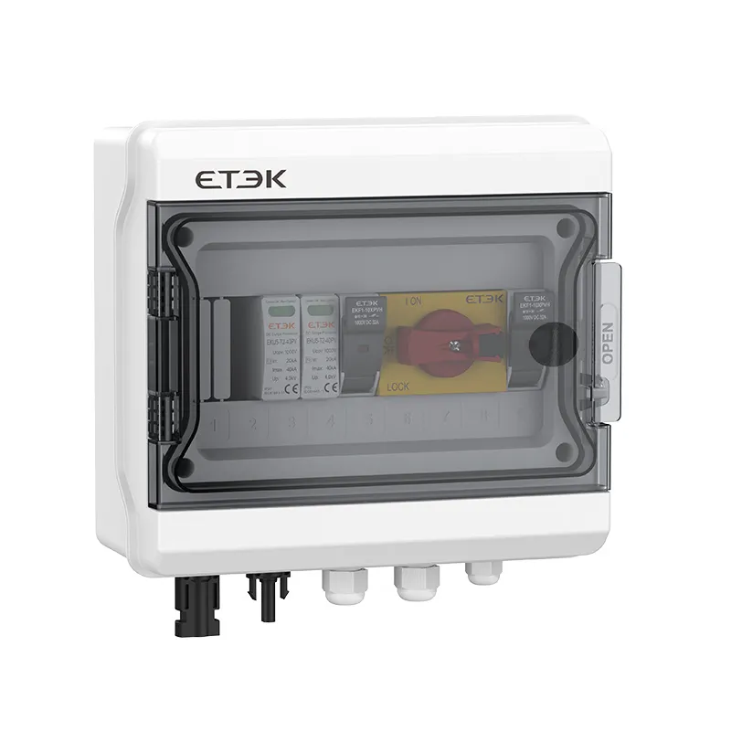
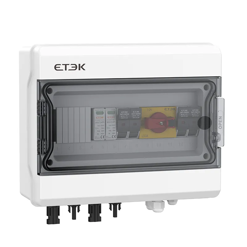
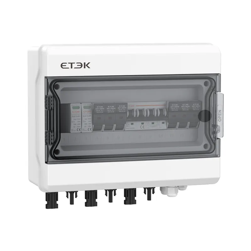
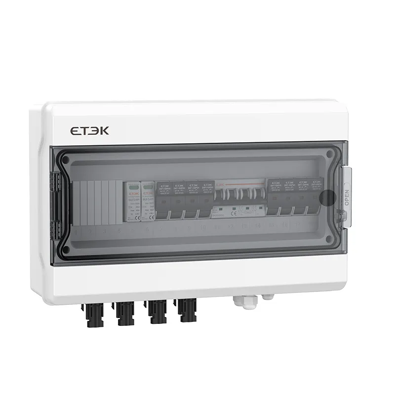
The modern evolution of this concept has led to the DC combiner box, an enclosure that does far more than combine strings. In well-engineered implementations, it acts as a comprehensive safety interface between the array and the inverter. Key functions integrated into such an enclosure typically include:
-
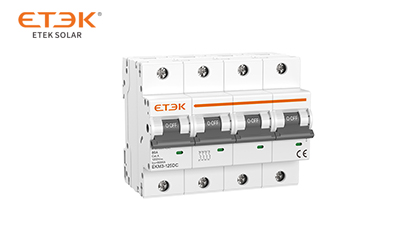
Per-string overcurrent protection: Usually with gPV-rated cylindrical fuse links or compact molded-case breakers specifically designed for the DC voltage and prospective fault currents of a PV array. These need to be carefully selected for 1.56 × Isc per NEC, factoring in ambient temperature derating.
-
Type 1 or Type 2 surge protection: Installed inside the same IP65-rated housing, dramatically simplifying the SPD connection to the DC bus and meeting the “as close as possible” installation rule of IEC 61643-12.
-
Load-break disconnectors: Often required by local utility regulations, a single-maintenance disconnect can isolate the entire DC side without sending a technician onto a hot roof.
-
Monitoring via current sensors or bus communication interfaces: Many modern units offer optional MODBUS RTU outputs that transmit per-string current and SPD status to a SCADA system—data that proves invaluable for proactive maintenance.

Each of these functions addresses a distinct failure mode identified by the Solar America Board for Codes and Standards (Solar ABCs). In their 2021 post-fire investigation guidelines, the board highlighted insufficient fault current coordination and the absence of local DC disconnects as recurring contributors to catastrophic PV fire spread. By consolidating these safety elements into one accessible location, field service teams can also perform routine thermal imaging inspections far more efficiently—identifying a loose battery connection before it becomes a 400°C arc, for example.
For designers exploring how these protections are mechanically laid out and how to balance enclosure dimensions with fuse count, it’s instructive to explore detailed enclosure layouts that illustrate common configurations for 600 V and 1000 V systems.
Best Practices for Minimizing DC Arc Flash Risks in the Field
No enclosure design compensates for poor installation habits. Drawing from feedback provided by utility-scale O&M teams across the Southwest U.S., several practical rules of thumb dramatically reduce the risk of DC arc flash and latent fire hazards:
-
Never install connectors under mechanical strain. A common practice—using the connector as a tension point to straighten a cable—creates a microscopic gap over thermal cycles. This gap becomes the initiation point for a series DC arc. Use cable ties on the cable sheath, not the connector.
-
Verify torque settings on all fuse holders and busbar screws during commissioning. A single loose connection on a DC bus carrying 100 A can generate sufficient heat to soften the enclosure’s thermoplastic, as documented in an internal NREL field study. Use a calibrated torque screwdriver.
-
Incorporate a maintenance bypass for SPD modules. Surge arresters degrade over time. A configuration that allows hot-swapping an SPD cartridge without powering down the entire array eliminates the dangerous temptation to delay replacement until the next scheduled shutdown.
-
Align fuse selection with array reconfigurations. When adding bifacial modules or higher-ampacity panels to an existing string, the original fuse rating must be recalculated. A fuse that was previously adequate may now nuisance-blow under normal reverse-current conditions—or worse, refuse to interrupt a real fault. Always cross-reference the inverter’s maximum reverse current rating.
These procedures may seem meticulous, but they reflect a collective learning from thousands of arrays that have operated without incident for over a decade. The common thread is accountability at the string level—something entirely dependent on a well-designed DC collection architecture. Operations teams looking to bring real-time string current monitoring into their asset management platforms can review smart monitoring implementation examples that demonstrate how MODBUS-enabled safety cabinets integrate with supervisory control.
Raising the Bar with Intelligent Monitoring and Robust Designs
As module-level power electronics proliferate, some project developers ask whether dedicated string-level protection enclosures will become obsolete. Data from the Engineered Wood Products Manufacturers Association (EWPM) demonstration site, which has tracked 84 rooftop systems for seven years, suggests the opposite. The site found that while microinverters and power optimizers reduce partial shading losses, they do not eliminate the need for overcurrent protection at the point of string parallel connection. In fact, with more sophisticated electronics on the roof, surge protection becomes even more critical, as the replacement cost of failed MLPE far exceeds that of a stand-alone fuse.
The ideal approach for a commercial or utility-scale installation is to select a DC aggregation solution that is configured for the specific voltage class, fuse type, and communication protocol of the project—rather than forcing a one-size-fits-all product into the design. This often means evaluating NEMA or IP ratings, enclosure material (stainless steel vs. glass-fiber-reinforced polyester), and whether the unit carries independent certifications like UL 1741 or IEC 61439-2 for low-voltage switchgear assemblies.
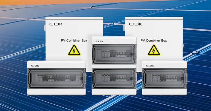
For a combiner box that meets these rigorous demands, ETEK provides a series of pre-engineered solutions designed to simplify compliance while keeping the total BoS cost predictable. Their engineering team has standardized on finger-safe fuse holders, transparent SPD status windows, and cable entry options that maintain the IP65 integrity even after field modifications—details that experienced electricians notice immediately. To understand how these design choices translate into measurable safety gains in corrosive or high-temperature environments, you can explore ETEK’s safety-focused PV aggregation systems.
The role of DC collection points in PV safety is often celebrated in design standards but undermined in execution. Giving these enclosures the same technical scrutiny as the inverter or the modules themselves is not an exercise in over-engineering; it’s a pragmatic response to failure data that has repeatedly shown the ignition source is rarely where you expect it. The next time a string-level fault lights up an alarm, the difference between a five-minute breaker reset and a five-week insurance claim may well come down to which enclosure is sitting between the array and the inverter house.
 - Enterprise-Protection-Solution-1052.webp)