The DC string combiner keeps tripping — not during a fault, but on a perfectly sunny afternoon. Meanwhile, the main DC breaker on your utility-scale battery bank hasn’t moved in months, but you’ve heard whispers about what happens when a high-current protector fails to interrupt a serious arc.
You’re not alone. PV installers and system operators consistently struggle with a deceptively simple question: What kind of DC protection belongs where?
The answer isn’t “one size fits all.” Residential arrays, commercial rooftop installations, and utility-scale solar farms have drastically different fault current profiles, and using the wrong device doesn’t just void warranties — it creates genuine fire hazards. NFPA data shows that 65% of solar system fires originate from electrical failures, with arc faults accounting for 42% and ground faults for 23%. That’s why understanding the gap between MCBs and MCCBs isn’t academic — it’s about keeping your system alive.
Let’s walk through four performance dimensions that determine which device belongs at each level of your PV architecture.
Current Capacity: Know Your Branch vs. Your Backbone
The most immediate difference between these two families comes down to how much continuous current each can handle.
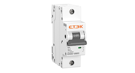
Miniature Circuit Breakers — the compact, DIN-rail mounted devices familiar to most residential and light commercial electricians — typically cover the low to medium end of the spectrum. Standard MCB ratings range from 1A up to roughly 125A. These devices excel at protecting individual string circuits, small combiner box branches, and battery interconnection points where current demands remain modest.
Molded Case Circuit Breakers, by contrast, are built for the heavy lifting. MCCB frame ratings commonly start around 15A and extend upward to 2500A or higher. In large-scale renewable systems, that high-end capability translates directly into main feeder protection, DC bus bars, and primary battery bank disconnects.
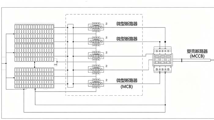
So where’s the dividing line? As a practical rule, MCBs serve the branch level (individual strings, combiner inputs), while MCCBs protect the backbone level (main DC distribution, inverter inputs, battery arrays).
A system isn’t “correct” just because it uses one type exclusively. A utility-scale array with nothing but MCBs on its main DC bus would be dangerously under-protected; a residential system with MCCBs at every string combiner would be over-engineered and needlessly expensive.
Voltage and Breaking Capacity: Where Fault Energy Becomes Real
Current rating tells you what a breaker can carry. Breaking capacity tells you what it can interrupt — and in DC solar applications, that distinction separates a safe shutdown from sustained arc flash.
DC circuits present a unique challenge that AC electricians often underestimate. In AC systems, the current naturally crosses zero 100–120 times per second, helping extinguish arcs. DC flows continuously in one direction with no zero crossing, meaning arcs can sustain themselves for hundreds of milliseconds unless the breaker’s arc extinguishing design is specifically engineered for direct current.
Breaking capacity — measured in kiloamps (kA) — quantifies the maximum fault current a device can safely clear. Standard DC MCBs typically offer 6–10kA interrupting ratings, which are sufficient for residential and small commercial fault scenarios. DC MCCBs, however, routinely reach 20–150kA, making them essential for commercial arrays and utility-scale farms where module counts can drive fault potentials far beyond MCB limits.
Voltage rating also diverges significantly. Many MCBs top out at 1000V DC, while MCCBs designed specifically for renewable energy — such as photovoltaic-grade molded case breakers — commonly support 1500V DC, the emerging standard for large-scale solar farms.
What this means for your system: If your potential fault current exceeds 10–15kA, MCBs simply cannot guarantee safe interruption. You need MCCB-grade breaking capacity at the main protection points — no exceptions.
Adjustability vs. Fixed Parameters: One Setting Doesn’t Fit All
This is where many experienced solar operators discover a major operational difference.
MCBs are generally equipped with fixed thermal-magnetic trip settings. The overload curve and instantaneous trip threshold are determined at the factory and remain unchanged throughout the device’s service life. That’s fine for branch circuits with known, stable loads, but it creates limitations when load conditions shift or need fine-tuning.
MCCBs, by contrast, typically offer adjustable trip settings — often covering both the long-time pickup current (overload protection) and the instantaneous pickup threshold (short-circuit protection). Some high-end molded case breakers incorporate electronic trip units with programmable curves, diagnostic memory, and communication capabilities.
For solar-plus-storage applications, adjustability delivers real value. A battery bank that starts at 200A of charge current but expands to 350A as modules are added doesn’t require full hardware replacement when the main breaker has adjustable settings already provisioned for the higher frame rating.
Why DC-Specific Design Matters More Than You Think
Neither MCBs nor MCCBs can be swapped directly from AC applications.
DC-rated devices incorporate several critical modifications that AC breakers lack:
-
Larger contact gaps to physically separate DC arc paths
-
Specialized arc chutes that force the arc into de-ionizing plates
-
Bidirectional current handling in a non-polarized design is crucial for PV systems, where reverse current can occur during maintenance or grid-down conditions
-
Corrosion-resistant materials for outdoor combiner boxes and exposed installations
Using an AC-rated breaker in a DC circuit — even one with a matching current and voltage label — invites arc persistence, contact welding, and eventual fire. NEC Section 690.9 explicitly requires DC-rated overcurrent protection for photovoltaic source and output circuits. The same principle applies globally under IEC 60947-2, the standard that governs low-voltage DC breaker certification.
Application Zones: A Decision Framework
Instead of choosing between MCB and MCCB for an entire system, think in terms of protection zones:
| Protection Zone | Recommended Device Type | Current Range |
|---|---|---|
| Individual string circuit (≤10 panels in series) | DC MCB (fixed trip, up to 63A) | Up to 63A |
| String combiner output (multiple parallel strings) | DC MCB or small-frame MCCB | 63–125A |
| Main Dbus/inverterer DC input | DC MCCB (adjustable trip) | 125–630A |
| Battery bank main disconnect | DC MCCB (high breaking capacity) | 250–1500A |
| Utility-scale array combiner main | Heavy-duty DC MCCB | 400–2500A |
Sizing also requires applying the 125% derating rule for continuous solar loads: your selected breaker’s rated current should be at least 1.25 times the maximum expected operating current — a requirement that applies equally to both MCB and MCCB selections.
Real-World Consequences: When Protection Fails
Here’s what the wrong choice looks like in practice.
Scenario A: A 300kW commercial rooftop array uses standard MCBs on the main DC bus. A short occurs between two series strings with high fault potential. The MCB’s 10kA breaking capacity is exceeded. The breaker fails to clear the arc, contacts weld closed, and the sustained arc ignites adjacent wiring. Damage: four destroyed combiners, three weeks of downtime, and an insurance claim of over $80,000.
Scenario B: A residential system with an MCCB on each string combiner — oversized for the actual loads. The long magnetic pickup threshold is set too low relative to the inverter inrush. Normal morning startup, current trips the breaker repeatedly, forcing the homeowner to manually reset three breakers every day before the system produces.
Scenario C: A 500kW DC-coupled storage system uses DC-rated MCBs for each of eight battery racks, then a single adjustable MCCB for the main DC bus. During a rack-level fault, only the affected MCB trips — not the entire system. The MCCB remains closed, preserving 87.5% of system capacity during the repair window.
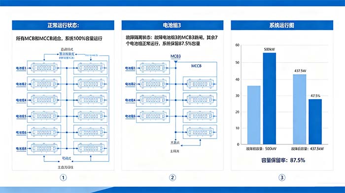
That final scenario highlights something crucial: protection coordination matters as much as device selection. When breakers are properly graded by trip curve and current rating, only the device closest to the fault opens — not the entire upstream system.
How Environmental Factors Reshape Your Decision
Outdoor solar installations test equipment in ways indoor electrical rooms never do.
Temperature extremes affect breaker performance significantly. According to application notes from major inverter manufacturers following IEC 60947-2, ambient temperature derating can reduce a breaker’s effective current-carrying capacity by 10–20% at temperature extremes. A breaker rated for 100A at 25°C might only safely carry 80A in a rooftop combiner box at 65°C.
DC MCCBs generally maintain more consistent performance across temperature ranges than MCBs, due to a more robust thermal compensation design. For systems operating in desert climates, high-altitude environments, or other challenging conditions, the performance stability of MCCB-grade protection justifies the additional upfront cost.
Making the Call: A Three-Step Process for Your Next Project
Step 1:Map your fault current boundaries: Calculate the maximum available fault current at each protection point in your system. If any point exceeds 10kA, MCBs are disqualified for that location.
Step 2:Zone your protection tiers: Assign MCBs to branch-level circuits under 125A with limited fault potential. Assign MCCBs to main feeders, bus bars, and any circuit where adjustable trip settings or high interrupting ratings are required.
Step 3:Verify DC rating and standards compliance: Confirm that every device you specify carries a DC rating (voltage, current, and interrupting capacity) and complies with either IEC 60947-2 or UL 489B, depending on your regional requirements.
Beyond Overcurrent: Building a Complete Protection Strategy
While this guide focuses on MCB versus MCCB selection, remember that comprehensive solar system protection requires a layered approach. Arc fault detection (NEC 690.11 mandates AFCI for DC PV circuits above 80V), surge protection, ground fault detection, and rapid shutdown capability all play essential roles in meeting modern electrical codes and reducing insurance liability.
The right overcurrent device — whether an MCB for string-level protection or an MCCB for main bus duty — forms the foundation. But it works best as part of a coordinated protection scheme where every component is specified, tested, and commissioned as a complete system.
For solar projects where reliability isn’t negotiable — and where protection device quality directly impacts system uptime and insurance compliance — investing in the right DC-rated protective equipment at every tier of your architecture pays back repeatedly over the system’s 25-year design life.
For site-specific coordination studies or assistance selecting the appropriate protection devices for your next PV or solar-plus-storage installation, visit the DC protection product lineup at ETEK Solar to explore rated options spanning from string-level breakers to high-capacity molded case configurations for main bus protection.
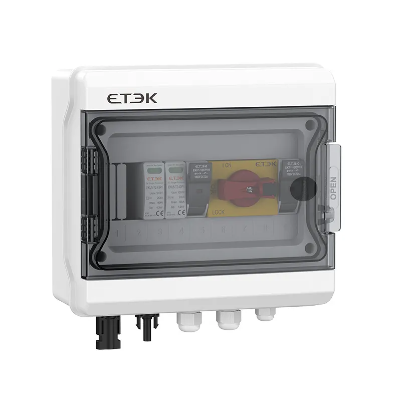
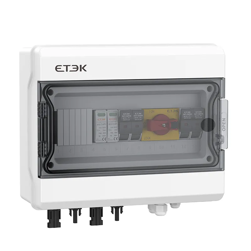
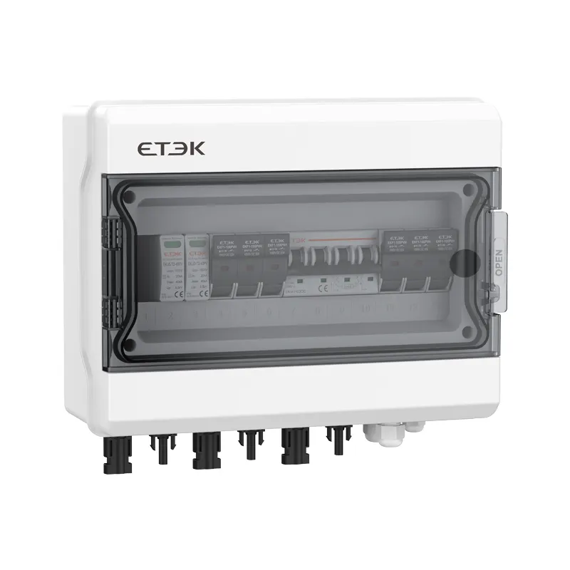
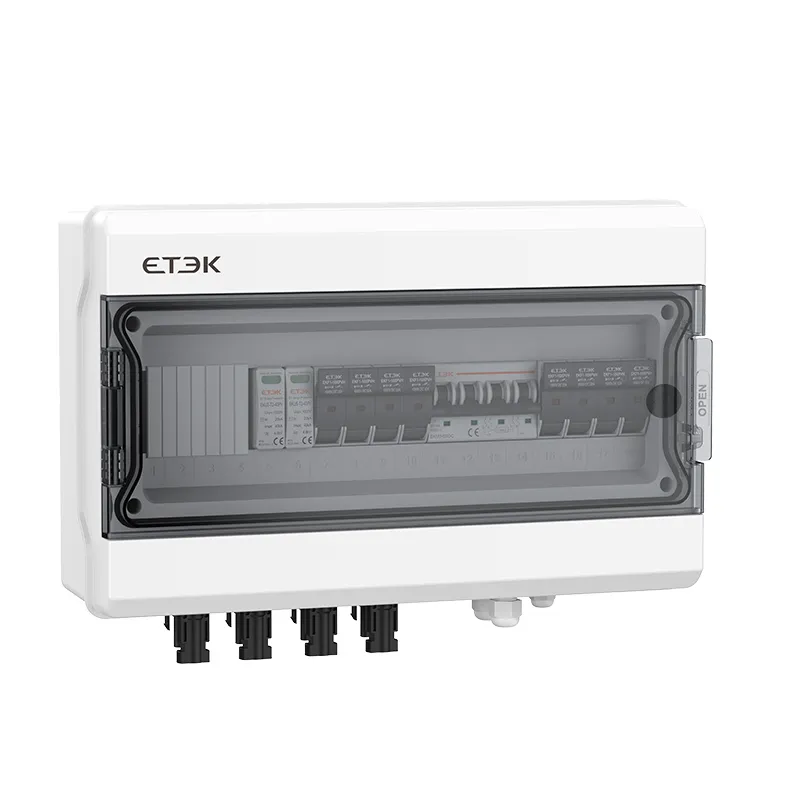
Note: The images in this article are for reference only.
-1640.jpg)
 - Enterprise-Protection-Solution-1052.webp)